C
E
Picor Corporation ?picorpower.com
QPI-8
Rev 1.5, Page 8 of 17
QPI-8
QUIETPOWER
?/DIV>
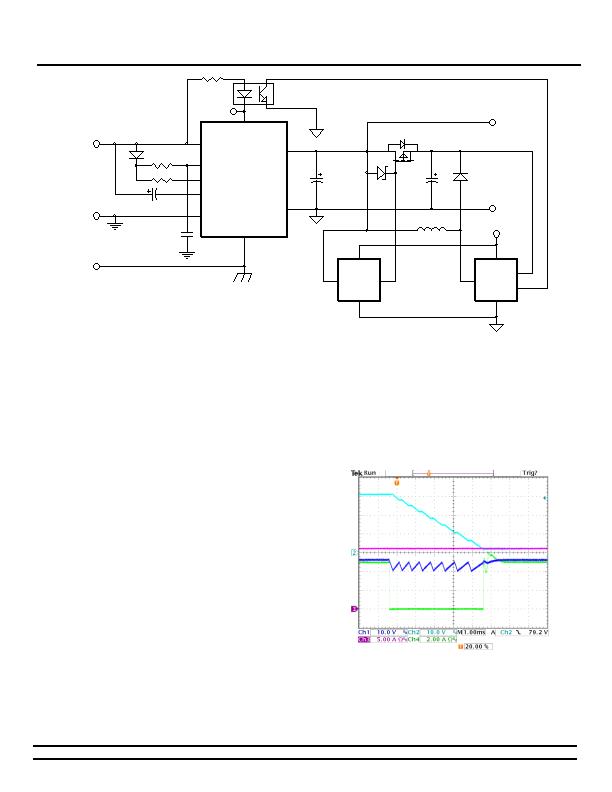
Figure 15 - Simplified Hi-Voltage Boost Circuit for Charging Bulk Storage Capacitors.
The circuit in Figure 15 shows a simplified version of a
PWRGD enabled boost circuit. The bulk storage capacitance
(CBULK) is initially charged to BUS+, along with the CIN
capacitor, through the body diode of the PFET. Once these
capacitors are fully charged, PWRGD enables the boost
converter to slowly charge the bulk capacitance to the
desired hi-voltage. When a low QPI+ voltage is detected, the
BUS VOLTAGE MONITOR circuit enables the PFET to discharge
some of its energy into the load converters CIN capacitor and
to the load. When the QPI+ rail reaches a pre-determined
limit, it shuts off the PFET and the rail starts to drop again.
This circuit acts much like a ripple regulator and will maintain
the output load until either the BUS voltage is restored or the
energy of the bulk capacitor is depleted.
The QPI-8 has a current sensing circuit that shuts off the
internal pass FET if a high di/dt is sensed across its internal
inductor. To avoid triggering this function, the PFET should be
turned on in its linear region. Typically, a zener diode can be
used to regulate the V
G-S
of the PFET and the amount of
energy discharged from the bulk capacitance. The waveforms
in Figure 16 demonstrate a zero-volt bus transient and the
response of the hi-voltage boost circuit. The storage caps
provide energy to sustain the load, while the bus is at zero for
5ms. The input current (green, CH4) drops to zero while the
load current (violet, CH3) remains constant. The voltage
across the bulk storage caps (light blue, CH2) slowly decays
while input voltage to the converter (blue, CH1) is regulated.
It is critical to keep the load current on the converters input
capacitor to less than 25mA during the initial start-up. This
limit is set by the current limit level and the duty cycle of the
circuit breaker timer, which is about 99% off time. An
excessive load will discharge the bulk capacitors during the
off time to a level where the on time charging current will
never charge the capacitor to the full bus voltage. Only after
Powergood has been established should the load be enabled.
Figure 16 - 5ms, 0V transient with 200W Load. CH1 and CH2
are offset by 50V DC.
PI+PI-
PI+PI-BOOST
发布紧急采购,3分钟左右您将得到回复。
相关PDF资料
SA56004HD,118
IC TEMP SENSOR DIGITAL 8SOIC
SC2463TSTRT
IC REG QD BCK/LINEAR 28TSSOP
SC338AIMSTRT
IC REG CTRLR DUAL POS ADJ 10MSOP
SC402BMLTRT
IC REG DL BCK/LINEAR SYNC 32MLPQ
SC403MLTRT
IC REG DL BCK/LINEAR SYNC 32MLPQ
SC418ULTRT
IC REG DL BUCK/LINEAR 20MLPQ
SC424MLTRT
IC REG DL BUCK/LINEAR 28MLPQ
SC4250LISTRT
IC HOT SWAP CTRLR 8-SOIC
相关代理商/技术参数
QPI-9
制造商:VICOR 制造商全称:Vicor Corporation 功能描述:Hot-Swap SiP With VI Chip EMI Filter
QPI-9-CB1
制造商:Vicor Corporation 功能描述:QPI-9LZ Filter w/ Hot-Swap Carrier Board for 24 V VI Chip "-CB" Boards up to 6A
QPI-9L
制造商:VICOR 制造商全称:Vicor Corporation 功能描述:VI Chip Input EMI Filters
QPI-9LZ
制造商:VICOR 制造商全称:Vicor Corporation 功能描述:Hot-Swap SiP With VI Chip EMI Filter
QPI-9LZ-01
制造商:VICOR 制造商全称:Vicor Corporation 功能描述:Hot-Swap SiP With VI Chip EMI Filter
QPI-X-EVAL1
制造商:VICOR 制造商全称:Vicor Corporation 功能描述:Evaluation Board for Active EMI Filters
QPL10000-M
制造商:Tamura Corporation of America 功能描述:
QPL10000-M-0
制造商:Tamura Corporation of America 功能描述: